 < Mechanical Adjustable Speed Drive
Planetary gear reducers are popular due to the way they transmit a great deal of power through a relatively small package. The central sun gear is surrounded by a number of planet gears which engage both the sun gear and outer ring gear. Due to the large number of gear teeth always in contact, a great deal of torque is transmitted.
An RXC drive is similar. The sun gear is replaced by an Input Disc, the planet gears by Cones, and the ring gear by a Control Ring. There are no gear teeth. Torque is transmitted through contact with the rolling edges of the cones.
If this were the complete system, and the Cone retainer were tied to the output shaft, it would operate as a simple speed reducer. In fact, Nidec Drive Technology Corporation does manufacture such speed reducers, for applications which cannot tolerate the speed ripple that results from engaging and disengaging gear teeth. No gears, no ripple.
However, the Ring-cone variable speed system separates the cones from the output shaft, and adds another contact element, the Cam Disc, to allow output speed changes.
As shown in the diagram right, the cones are somewhat “umbrella shaped,” with a stem area. When placed in a retainer, the cones are held at such an angle that a portion of the cone surface is horizontal. This horizontal surface makes contact with the Control Ring.
The Input Disk is tied to the input shaft, usually rotating at motor speed, and contacts the Cones under the “umbrella,” on a machined shoulder. The Cam Disc is tied to the output shaft, and contacts the Cones on the underside of their outer edge. The Control Ring is tied to the body of the drive, so it does not rotate. It makes contact with the Cones along the horizontal surface, and can slide from near the outer edge to near the center of the Cones.
The Control Ring is the variable speed element in the Ring-cone system. When moved toward the center of the Cones, it causes them to rotate faster, as they orbit the Input Disc. Moved toward the outer edge, the Control Ring causes the Cones to rotate more slowly. As the outer edges of the Cones change speed, the Cam Disc (and therefore output shaft) also changes speed.
 As the Cones spin, they are also orbiting the Input Disk, as with a typical planetary gear system. If the Control Ring is adjusted such that the orbit speed and Cone edge speed cancel each other, the output shaft will remain stationary under power. This is a unique feature of the Ring Cone system.
The Ring-cone system is essentially a variable speed reducer. It’s output speed is the result of a changing reduction ratio, which means torque increases as the output speed decreases. This is what makes the Ring-cone system superior to the common AC variable frequency drive, a constant torque system.
To further take advantage of the low speed / high torque relationship, the Ring-cone design adds a spring-loaded cam system which forces the friction components more tightly together as the load increases. This action also causes the Cones to move relative to the Control Ring, slowing the output speed momentarily. The combination both prohibits slip between components, and automatically increases the output torque, two actions which may resolve the increased load.
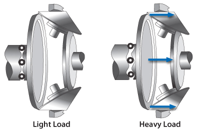 The result is a system that will stall the properly sized input motor before it will slip. When the load decreases, the spring-pressure on the components relaxes, reducing system stress and allowing the output speed to return to normal. Again, a unique feature which makes the Ring-cone system ideal for the toughest applications, especially those subject to wild fluctuations in load.