Reduction Mechanism
Strain wave (harmonic) gear technology centers on the elasticity and flexibility properties of a uniquely shaped metal structure. The strain wave gear set has three key elements; the elliptical wave generator, the flexspline, and the circular spline.
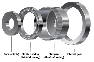 The elliptical wave generator subassembly is comprised of two components: an elliptical shaped disk and an outer ball bearing. The disk is inserted into the bearing, giving the bearing an elliptical shape as well. The wave generator assembly is the input section of the gear set.
- The flexspline is the internal component that relies on unique elasticity properties to accommodate an elliptical deformation pattern. The sides of the cup gear are very thin, but the bottom of the cup gear is thick and rigid. This results in significant flexibility of the walls at the open end of the cup; but then the cup gear exhibits high rigidity at the closed end of the cup. Teeth are positioned radially around the perimeter of the open end of this cup gear.
- The flexspline fits very tightly over the wave generator subassembly. When the wave generator is rotated, the flexspline deforms to the shape of a rotating ellipse but does not rotate with the wave generator.
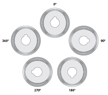
- The circular spline is a rigid circular ring with teeth located on the interior perimeter. The wave generator and flexspline are placed inside this inner ring gear, meshing the teeth together. Because the flexspline cup gear has a deformed elliptical shape, the teeth will only mesh in two regions 180 degrees from each other, along the axis of the ellipse.
- As the wave generator subassembly rotates, the group of teeth of the flexspline that are engaged with those of the circular spline ring gear changes. The major axis of the flexspline actually rotates with the wave generator, therefore; the points where the teeth mesh revolve around the center point at the same rate as the wave generator.
- The reduction is accomplished through a tooth count differential between the flexspline and the circular spline. For every full rotation of the wave generator subassembly, the flexspline rotates a minor amount backward because it has less teeth than the circular spline.
Reduction Ratio
The rotation the wave generator subassembly results in a much slower rotation of the flexspline in the opposite direction. For a harmonic gearing mechanism, the gearing reduction ratio can be calculated from the number of teeth on each gear:
As an example, if there are 202 teeth on the circular spline and 200 on the flexspline, the reduction ratio is
(200 – 202)/200 = -0.01
Therefore, the flexspline rotates at 1/100 of the speed of the wave generator assembly and in the opposite direction. This method of reduction permits a variety of ratios to be set without changing overall gear set shape, increasing its weight, or adding reduction stages. The variety of reduction ratios possible is restricted by the structural tooth size limitation for any given configuration.