 The Circulute also can be a potential solution for servo motor applications, when the performance benefits and durability are necessary. Nidec Drive Technology Corporation can provide the appropriate input motor flange to match your specific servo model. The internal dual pin-housing of the cycloidal gearbox can be pre-loaded, in order to reduce the output shaft backlash to less than 6 arc-minuts. At a 3,000 RPM input speed , the Circlute can handle a maximum motor capacity of 12kW and provide single reduction ratios ranging between 11:1 to 71:1.
Nidec DTC has vast applications knowledge and much expertise with motion control projects from our high-precision product range and our motor partnerships. Please consult with us about any of your specific servo applications, and we can help you determine if the servo Circulute is an appropriate option for your equipment.
Model Codes | Selection Procedures | Performance Specifications | Dimensions
Selection Procedure for Servo Motor Applications
- Determine the load classification from the Load Classification Table.
- Select the Circulute 3000 Reducer service factor from the Service Factor Table (below) for the application taking into consideration the load classification and duration of service.
- Calculate the required reduction ratio by dividing the rated servo motor speed (rpm) by the required output shaft rpm.
- Multiply the servo motor capacity (kW or HP) by the service factor and select the Circulute 3000 Reducer from the selection table based on servo motor rated speed and backlash required from the Performance Specification Tables with a rating that exceeds this calculation. This is the tentative selection.
- Calculate the average torque by using the formula below, making sure that average torque is less than the nominal torque value of the selected Circulute 3000 Reducer (T1) as shown in our rating tables.
- Multiply the selected Circulute 3000 Reducer nominal torque value (T1) as shown in our rating tables by 1.5. Make sure that this value exceeds the acceleration torque of the application.
- Select the required mounting type from the Model Codes.
- Select the required mounting position from Model Codes.
- Check the overhung and/or thrust loads on the output shaft if connected to the load by either a sprocket, sheave, pulley, or gear on the following Dimensions.
- Configure the Model Codes, noting backlash and any unusual operating or ambient conditions. Contact Nidec DTC Customer Service for questionable items, or applications assistance.
Service Factor Table
| Duration of Service | Load Classification | ||
|---|---|---|---|
| Uniform (U) | Moderate Shock (M) | Heavy Shock (H) | |
| Up to 10 hours per day | 1.00 | 1.20 | 1.40 |
| 24 hours per day | 1.25 | 1.40 | 1.60 |
Formula
| Where | Tave: Average torque |
| Ta: Acceleration torque | |
| Tr: Running torque | |
| Td: Deceleration torque | |
| ta: Acceleration time | |
| tr: Running time | |
| td: Deceleration time |
Miscellaneous Engineering Information
Ambient Temperature
The ambient operating temperature range of the Circulute 3000 Reducer is from 32oF to 104oF (0oC to 40oC). Contact Nidec DTC Customer Service if operating conditions fall outside of this range.
Backlash
The standard backlash option is approximately 1° (60 arc-min). The precision backlash option is less than 0.1° (6 arc-min).
Direction of Rotation
The input shaft can be rotated in either direction. For single reduction reducers, the output shaft rotates in the opposite direction of the input shaft. For double reduction reducers, the output shaft rotates in the same direction as the input shaft.
Exact Ratio
All Circulute 3000 reduction ratios listed in this catalog are exact.
Thermal Ratings
The high efficiency of the Circulute 3000 Speed Reducer results in thermal ratings which exceed its mechanical rating in all cases. Therefore, it can be run continuously at any of the input speeds in this catalog.
Table 1 Input Shaft Thrust & Overhung Load Capacity (lbs)
| Frame Size | Load Type | Input Shaft Speed (rpm) | |||
|---|---|---|---|---|---|
| 580 | 870 | 1165 | 1750 | ||
| A | OHL Thrust | 260 | 260 | 230 | 200 |
| 130 | 130 | 115 | 100 | ||
| B | OHL Thrust | 260 | 260 | 230 | 200 |
| 130 | 130 | 115 | 100 | ||
| C | OHL Thrust | 400 | 390 | 350 | 310 |
| 200 | 195 | 175 | 155 | ||
| D | OHL Thrust | 600 | 600 | 540 | 480 |
| 300 | 300 | 270 | 240 | ||
| E | OHL Thrust | 1,300 | 1,100 | 1,000 | 880 |
| 650 | 550 | 500 | 440 | ||
| F | OHL Thrust | 1,700 | 1,500 | 1,300 | 1,200 |
| 850 | 750 | 650 | 600 | ||
Notes: Overhung load ratings are based on the load being applied to the center of the shaft.
Ratings shown are based on a combined overhung and thrust load being applied to the shaft.
Output Shaft Overhung Load
When a sprocket, sheave, pulley, or gear is mounted on the output shaft or on the input shaft, an overhung load is applied to the shaft. It is necessary to check whether the shafts of the reducer will allow the required overhung load.
Overhung Load Calculation
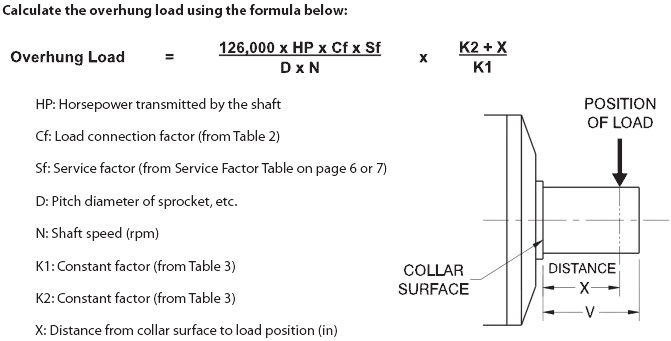
Table 2 Load Connection Factor: Cf
| Type of Connection | Factor |
|---|---|
| General Purpose Chain | 1.00 |
| Machined Gear, Pinion, or Syncronous Belt | 1.25 |
| V-Belt | 1.50 |
| Flat Belt | 2.50 |
Table 3 Output Shaft Overhung Load Capacity (lb)
| Frame Size | Output Shaft Speed (rpm) | Constant Factor | |||||||||
|---|---|---|---|---|---|---|---|---|---|---|---|
| 40 & Below | 50 | 60 | 80 | 100 | 125 | 150 | 200 | 250 & Above | K1 | K2 | |
| A | 780 | 780 | 780 | 780 | 780 | 764 | 715 | 650 | — | 5.37 | 4.67 |
| B | 1,284 | 1,284 | 1,284 | 1,284 | 1,284 | 1,268 | 1,186 | 1,073 | 934 | 5.67 | 4.67 |
| AB | |||||||||||
| C | 2,763 | 2,600 | 2,438 | 2,275 | 2,113 | 1,950 | 1,788 | 1,625 | 1,414 | 6.83 | 5.55 |
| AC | |||||||||||
| D | 5,038 | 4,713 | 4,550 | 4,063 | 3,738 | 3,575 | 3,250 | 3,088 | 2,687 | 8.26 | 6.38 |
| AD, BD | |||||||||||
| E | 7,475 | 7,475 | 7,475 | 7,475 | 7,313 | 6,825 | 6,338 | 5,688 | — | 11.4 | 9.25 |
| BE, CE | |||||||||||
| F | 12,188 | 12,188 | 11,538 | 10,563 | 9,750 | 9,100 | 8,613 | 7,800 | — | 13.9 | 11.1 |
| CF, DF | |||||||||||
Notes: These ratings are based on thrust load = 0.
Contact Nidec DTC Customer Service for applications which have combined overhung & thrust loads.